~/contents
I’ve become interested in the use of ATTiny chips for small projects that don’t require many I/O pins. This is a family of small 8-bit MCUs. The bare chips require an AVR programmer, but ATTiny85 breakout boards are widely available. Unusually, the Digispark breakout boards are a little cheaper than the bare chips themselves.
The ATTiny85 is commonly available as a Digispark Breakout, which has a micro-USB and does not require an AVR programmer. They can be powered via USB (5V) or the VCC pin (7 to 12V), 6 I/O pins (or 5, if the reset pin has not been disabled), and 8k flash memory (the bootloader requires 2k). They also have I2C, SPI, and PWM on 3 pins. These boards should be running the micronucleus tiny85 bootloader. You will need to install drivers. The boards can be added to the Arduino IDE like so:
File > Preferences > Additional Boards Manager URLS > http://digistump.com/package_digistump_index.json
Then go to Board Manager and install the Digistump AVR Boards. The board is Digispark Default.
These boards are a little different than the other ones I’ve used, the Port is greyed out, which threw me initially. When you plug the Digispark in it should be listed as a Libusb-win32 device. When you attempt to upload a sketch, you will see:
Running Digispark Uploader...
Plug in device now... (will timeout in 60 seconds)
> Please plug in the device ...
> Press CTRL+C to terminate the program.
> Device is found!
Plug your board after you start the upload process.
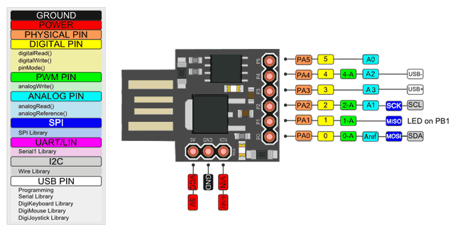
PINS
1 - PB0 / MOSI
2 - PB1 / MISO
3 - PB2 / SCK / AD1
4 - PB3 / AD3 (Reserved for USB)
5 - PB4 / AD2 (Reserved for USB)
6 - PB5 / RES (Reset may be disabled on some boards)
Two pins are reserved USB usage and will be unavailable if you are using USB. Library availability and memory size can be an issue. There are some Tiny-fied libraries, for instance TinyDHT, so keep an eye out for that. One thing that makes debugging particularly troublesome is serial monitor is not supported. There is a software solution, but it takes up a lot of memory. I had no issue porting over a simple program that required no libraries, so the Digispark was a very good solution for that project. The board is about half the size of a Nano, so I can see the advantage in simple applications that need a small footprint. That being said, these boards can have a lot of issues, and clone boards have become so affordable generally if there’s any chance you’d need more memory or pins you might as well go with a Nano or some other board.
Issues with the Micronucleous Bootloader and USB Communication
After working with these boards a bit I have begun to run into issues with the USB. The Digispark uses software USB and at times only works intermittently. At one point I thought I might need to reflash the bootloader. Burning a Micronuclous bootloader requires a few extra steps because the t85 hex file is too big and has to be compressed, which is a bit of a nuisance on Windows.
Upgrading can be done from the command line. After adding the upgrade hex file to my micronuclous.exe folder the command was:
micronucleus --run upgrade-t85_default.hex
Having gone back and forth, I think the software USB is a bit finicky.
Resources for the bootloader:
- https://gist.github.com/Ircama/22707e938e9c8f169d9fe187797a2a2c
- https://electronics.stackexchange.com/questions/161361/burn-micronucleus-bootloader-to-use-attiny85-via-usb-avrdude
- https://dumbpcs.blogspot.com/2015/11/programming-your-attiny85-with-arduino.html
- http://yourtechbhai.com/2017/02/10/burn-or-flash-micronucleus-bootloader-on-digispark-attiny-using-arduino-uno/
- https://digistump.com/board/index.php?topic=2833.0
ISP Programming
The issues with USB, and the fact the bootloader takes up 2k, made me want to move away from that process. Since I have had good experiences using my Uno as an ISP programmer I wanted to see if I could do the same for the Digispark. In some cases the Digispark’s reset pin is disabled by default (this is so the board will have an extra pin for use; if you are unable to use P5 as GPIO then reset has not been disabled on your board and you can program via ISP as normal). If the reset pin is disabled the board must be “unlocked” with a high-voltage programmer. To test, simply attempt to blink an LED on P5.
Resources:
- http://www.rickety.us/wp-content/uploads/2010/03/hv_serial_prog.pde
- https://www.instructables.com/id/How-to-unlock-Digispark-ATtiny85-and-convert-it-to/
- https://arduinodiy.wordpress.com/2015/05/16/high-voltage-programmingunbricking-for-attiny/
- http://www.electronics-lab.com/recover-bricked-attiny-using-arduino-as-high-voltage-programmer/
- https://github.com/J-Rios/Digispark_Unbricking