~/contents
- Updated 10/27, added notes regarding Colorduino Hell
- Updated 11/28, FTDI module ahoy
1088AS 8x8 3mm MAX7219 Common Cathode Matrix Display
These red LED matrix modules are plug and play and they can be cascaded. Since they are driven by a MAX7219 they only require 3 pins for operation. The LedControl library can be found and installed in the Arduino IDE via Tools > Manage Libraries. Brainy Bits How to Control MAX7219 LED Matrix tutorial shows how to cascade 2 matrixes. The code generates a ridiculously cute little space invader. These modules are very easy to use and good for experimentation.
The majority of these matrix modules are red, but I was able to find a few blue, yellow, green, and white displays. Otherwise if you want other colors or RGB you can get a shield or build your own circuit with an off-shelf matrix using either an LED driver like the MAX7219 or shift registers, or the HT16K33, which is used in the Adafruit backpacks. Tronixstuff’s Arduino and the MAX7219 LED Display Driver IC is very informative.
CILE 2088RGB 8x8 5mm Off-Shelf LED Common Anode Matrix Display
I impulse ordered this RGB matrix thinking I’d sort it out when it arrived and quickly learned RGB matrixes are a real can of worms. This 60x60mm RGB matrix display can be driven by a shift-register like 74HC595, and the ICs can be cascaded to drive all three colors for all 64 LEDs. It’s a lot of wiring, to say the least, and people who want something more plug-and-play can pay a bit more for one of the many shields on the market (all have names like RGBuino, Colorduino, Rainbowduino, etc.). This particular matrix is compatible with the Colorduino. Most of these utilize MBI5168, a M54564 transistor array, and DM163. I have also seen use of TLC5940 and MIC5891, which is a shift-register with PNP darlington transsitors built into its output. You will want to verify library support before you purchase a shield.
I honestly spent a stupid amount of time researching drivers to see if I could build my own driver board. MAX7219, HT16K33 (which can drive 1 bi-color or 2 single-color displays), and HT1632C (which is sometimes used to drive 4 to 6 matrix panels) are all designed for common cathode. See phatIO’s LED display Control with the ht16k33 for more information as well as deshipu’s D1 Mini Matrix Shield logs. I also looked into the possibility of using different types of breakout boards to simplify the build, including basic 74HC595 breakouts, a 24-channel TLC5947 LED driver board, or a couple of 16-channel TLC5940 LED driver board. Of those the former seemed promising but I couldn’t find a tutorial or an example of someone using it on one of these 8x8 RGB anode matrixes. I really couldn’t find a 4-74HC595 board that wasn’t overly expensive for my use case, I think because people with PCB design knowledge could trivially design one. Considering a Colorduino can be had for less than $10, I didn’t want to spend more than that.
If you are interested in this subject I suggest Marc Merlin’s excellent Driver for direct driving single to 3 color LED Matrices with software PWM post and Sunfounder’s RGB LED Matrix Driver Shield wiki page.
Cascading 74HC595
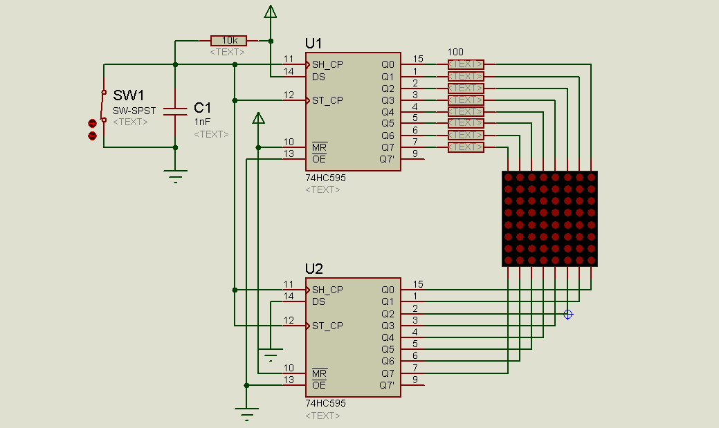
I had four 74HC595s on hand, so I had to give the old school method a try. The 2088RGB datasheet floating around isn’t great, but it tells us the red LEDs have a forward voltage of 1.8 to 2.7 and the green and blue LEDs have a forward voltage of 3.0 to 3.3. There is no pinout data. theraspberryblonde’s pinout notes for the ORM-2088RGB matched this display as well. The display has two 16-pin rows, which map as:
TOP ROW: ANODE 1-4, GREEN 1-8, ANODE 5-8 BOTTOM ROW: RED 1-8, BLUE 1-8
I originally attempted a single-color setup with one 74HC595 chip (Coutinho’s Using a 74HC595 to control a LED Matrix. I followed-up by adding a second 74HC595 for the anode pins using MarkKl’s Arduino 8x8 Led Matrix Driver With 2x 74HC595 Shift Registers. The bildr post Can you move over? The 74HC595 8-bit shift register provides a nice clear diagram of cascading 2 chips. Pins QA - QH map to the matrix. 14/SER, 12/RCLK, and 11/SRCLK map to digital pins. QH maps to the SER pin on cascading chips. Once you understand how to cascade the 74HC595s it’s just a matter of having the wiring and space to include the remaining colors.
Take my word for it–using 4 shift registers to power a LED matrix is an educational exercise and probably not a practical one if you can’t make a custom PCB. I was able to use Michael Kamprath’s Shift Register LED Matrix Lib but I had so many wiring and performance issues I knew it would take a lot of time and energy to get an implementation I could use, whereas for $6 to $10 you can get a Matrix shield and be done with it.
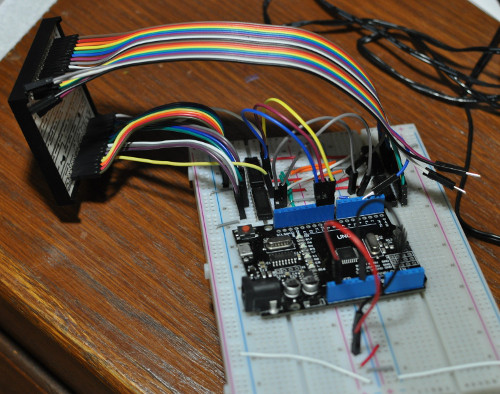
To provide some visual perspective, here’s the tidiest 4-shift register implementation I have made, sans the 8 resistors that should probably be in there.
Colorduino V2.0
I picked up a Colorduino clone (Colorduino V2.0) made by ICduino, who no longer lists it on their website, so I rely on this schematic. It uses a DM163 LED driver and has it’s own ATMega328P chip. It can be powered with 5V from the pin headers or 6.2V to 7.5V on the terminal side, with a warning more than 7V will cause overheating and 9V may burn the board. Note the terminal/headers switch on the board. According to the seller it can be programmed via FT323 on the serial pins. The module has its own ATMega328 chip and needs to be programmed separately and utilized via I2C alongside the main microcontroller.
When attaching the matrix, make sure the pins match. You can confirm the matrix is working by applying 5V and GND to the pins. When power is supplied the demo starts. In this case it’s a brief color block in need of gamma correction and the letter A in blue LEDs.
Burning a Bootloader
I had issues uploading sketches and decided to burn a bootloader to the Colorduino. You may not need to do this. The ICSP headers are marked on the back of the board. Upload the Arduino ISP to the Uno (File > Examples > Arduino ISP). The 6 ICSP pins at the top of the Colorduino need to be connected to the corresponding digital pins on the Uno.
Colorduino Pin 1 (MISO) > Uno digital pin 12 (MISO)
Colorduino Pin 2 (5V) > Uno 5V
Colorduino Pin 3 (SCK) > Uno digital pin 13 (SCK)
Colorduino Pin 4 (MOSI) > Uno digital pin 11 (MOSI)
Colorduino Pin 5 (RST) > Uno digital pin 10 (SS)
Colorduino Pin 6 (GND) > Uno GND
Plug the Uno into your PC, then select Arduino Duelimenova as the current board.
Tools > Board > Arduino Duelimenova Tools > Programmer > Arduino as ISP Tools > Burn Bootloader
FTDI
You can upload sketches via FTDI cable or module (spoiler: I was unable to upload with either of my FTDI cables or other Arduinos, but a FT232RL module worked great). If you cannot locate a COM port for your FTDI device you may need to install FTDI drivers. If you do not have a RTS/DTR connection on your cable you will have to use the manual reset button the board.
FTDI -->-- Colorduino
Red (5V) > 5V
Black (GND) > GND
White (RXD) > TXD
Green (TXD) > RXD
Yellow (RTS/DTR) > DTR
When I attempted to upload a Colorduino example with my cables the upload process would time out with some form of access denied error. I reloaded the FTDI drivers, tried different Boards (Uno, Nano), tried uploading a bootloader via Gammon’s method. I also tried programming with Uno as ISP. Invariably whenever I tried to upload a sketch I’d get an error along the lines of:
avrdude: stk500_recv(): programmer is not responding
avrdude: stk500_getsync() attempt 1 of 10: not in sync: resp=0xed
avrdude: ser_send(): write error: sorry no info avail
avrdude: ser_recv(): read error: Access is denied.
I finally had success with a FT232RL FTDI module. With it, lincomatic’s ColordiunoPlasma demo uploaded like a charm.
Colorduino & Friends with I2C
The Colorduino has a few pins broken out, but not many. If additional modules or inputs are needed it is common to use two Arduinos, having a leader/main Arduino handle input and communicate that data to the follower/helper Colorduino. This can be done via serial, but it is probably best to use I2C. Nick at 123led has posted his sample Colorduino I2C code and there are many resources online about connecting Arduinos via I2C.
Colorduino References:
- https://github.com/lincomatic/Colorduino
- https://github.com/MartyMacGyver/Colorduino
- https://www.falatic.com/index.php/99/trying-out-my-new-colorduino-v2-0-first-impressions-and-tips
- https://forum.arduino.cc/index.php?topic=172304.0
- https://web.archive.org/web/20150506073240/http://katalytischerkonverter.com/2014/10/04/colorduino-tutorial/
- https://www.instructables.com/id/Lampduino-an-8x8-RGB-Floor-Lamp/
Additional LED Matrix References
- https://bloglabdsd.files.wordpress.com/2015/02/an-1216-introduction-to-driving-led-matrices.pdf
- https://medium.com/adventures-in-electronics/my-led-matrix-needs-a-little-tlc-d739ac60c152
- https://www.instructables.com/id/Multiplexing-with-Arduino-and-the-74HC595/
- https://learnpic32.blogspot.com/2014/06/controlling-rgb-led-matrix-with-shift.html
- http://francisshanahan.com/index.php/2009/how-to-build-a-8x8x3-led-matrix-with-pwm-using-an-arduino/
- https://www.youtube.com/watch?time_continue=2&v=wXvs0CrRPIw
- http://oomlout.com/8X8M/8X8M-Guide.pdf
- https://www.instructables.com/id/Arduino-8x8-RGB-LED-Matrix-Controller-With-4-Shift/
- https://www.instructables.com/id/64-pixel-RGB-LED-Display-Another-Arduino-Clone/
- https://arduinoleonardo.blogspot.com/2014/05/2088rgb-5-matriz-rgb-de-8x8-de-anodo.html
- http://tinkering-arduino.de/blog/2013/02/25/8x8-led-matrix-mit-color-shield-teil-1/
- http://zaidpirwani.com/wp-content/uploads/2012/08/Led-Matrix-Manual-74HC595-Shift-Register-Test.png
- https://maker.pro/arduino/projects/arduino-led-matrix
- https://www.youtube.com/watch?v=iUoXbRhtbqs
- http://www.gunook.com/nexys-2-licht-dodger-spiel/