~/contents
I like Arduboy so much I wanted to explore it further, which meant leaving my Arduboy Nano Clone behind in favor of a Pro Micro which would have better software compatibility. The Arduboy Quickstart Guide walks us through the recommended libraries.
Current Build
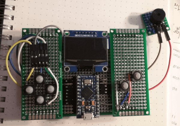
I now have a modular devboard, inspired by cheungbx’s Ardubaby which has button and joystick hats. I wanted the board, screen, and inputs to be as modular as possible with a horizontal form factor. The pro micro can easily be swapped out, as can the inputs.
Basic Clone
Wiring
I first wired up the SH1106 SPI OLED and got it working, then plopped my Pro Micro into the Arduboy shield I’d made. I was able to run the ArduboyTest sketch, located in Examples > U8G2 > u8x8 > ArudboyTest by applying this U8x8 constructor:
U8X8_SH1106_128X64_NONAME_4W_HW_SPI u8x8(/* cs=*/ 10, /* dc=*/ 9, /* reset=*/ 8);
OLED | Arduino GND | GND VCC | VCC CLK/D0/SCL/SCK | SCK (D15) MOSI/SDA/D1 | MOSI (D16) RES | RST (D8)* DC/A0 | DC (D9)* CS | CS (D10)*Buttons | Arduino UP | A0 RIGHT | A1 LEFT | A2 DOWN | A3 BUTTON A (LEFT) | D7 BUTTON B (RIGHT) | D8
You will notice a conflict, both RES and Button B are mapped to D8. For now it can be changed using the below:
U8X8_SH1106_128X64_NONAME_4W_HW_SPI u8x8(/* cs=*/ 10, /* dc=*/ 9, /* reset=*/ 6);
Mr. Blinky’s Arduboy Homemade
Mr. Blinky’s Arduboy Homemade Package was the next step. This package has support for many different displays and wiring schemes and helps unify homebrew devices. Mr. Blinky has provided a pin wiring table. I attempted to follow the alternate wiring listed, but found I only had a blank screen.
After digging around on the forums I read Pavlov Roman’s SH1106 post and changed the wiring as follows:
OLED pin RES -> Digital pin 6 of arduino OLED pin DC -> Digital pin 4 of arduino OLED pin CS -> GND pin of arduino
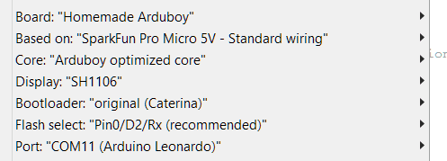
At least now I was getting image again! This time, I was getting the first few lines followed by a lot of static. After some more fiddling I realized the issue was I had Arduboy libraries installed, and per Mr. Blinky’s instructions they should all be removed before uploading with the Arduboy Homemade. I made the change, and the game works. The board settings I use are:
The larger screen was definitely worth figuring out.
FerJerez has listed the core changes needed for this OLED.
Joystick
My next task is figuring out how to map the Arduboy’s native 4-button D-pad to the nifty little Adafruit Analog Mini Thumbstick. The thumbstick is actually two potentiometers, so it requires a software modification. If I’d gone with a 5-way switch, like I originally thought I might, there would be no software modifications. CatDadJynx’s homemade Itsybitsy Arduboy thread has a discussion of how this is done and a codesnippit for modifying Arduboy2Core::buttonsState.
I found Stan’s Arduino Joystick Module Example useful for reading the joystick values.
I’m trying to figure out how to extend the default classes. filmote’s Don’t like the default behaviour? Extend and overwrite it! will prove useful.
Expanded Flash Storage
Upcoming… flash storage! Wheee! I ended up getting W25Q32JVDAIQ, which is 4MB. That’s much smaller than I would have liked, but it will be okay for the Arduboy.
Mr. Blinky’s Flash cartridge post lays out the concept. The DIP8 pinout is so, and our operating voltage range is 3.0 to 3.6.
1 CS | 8 VCC
2 DO | 7 HOLD
3 WP | 6 CLK
4 GND | 5 DI
I have been toying with the idea of trying to reduce the Pro Micro’s voltage to 3.3 without a voltage regulator and level shifter, but after some research I concluded there isn’t a good way to do this without having to do some soldering I can’t reasonably do. There’s a discussion on the Arduino forum about the jumpters and voltage.